
Model Builder 4.08 and later supports variable bandwidth for the radio objects. This allows the user to accurately simulate the bandwidth characteristics of various radios, including wide and narrow band selection. In previous versions of Model Builder, the radio bandwidth was fixed at 25 KHz.
The bandwidth parameter is straight-forward. Simply take the bandwidth value, divide it in half, and add or subtract the result from the center frequency to obtain the operating band of the radio. For example, a radio with a center frequency of 1 MHz and a bandwidth of 25 KHz operates in the band 0.9875 to 1.0125 MHz. The default bandwidth for all radio modes is 25 KHz.
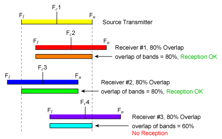
The % overlap field (%ovr in the radio object) requires a bit of explanation. This field answers the question, “How much of the receiving radio’s frequency band must overlap the transmitter’s in order for the transmitter to be in-tune?” Refer to figure 1 for a graphical depiction of overlap.

Calculated % overlap = (Overlap of the 2 bands / Transmitter bandwidth) x 100
If the calculated % overlap value is greater than the %ovr field in the receiver, the transmitter is considered to be in-tune. If the calculated % overlap value is less than the %ovr field in the receiver, the transmitter is considered to be an in-band jammer.
For radios using the same bandwidth, a %ovr value of 100 means that the center frequencies of the two radios must be identical. Any change in the center frequencies of one of the two radios will prevent communications between them. Conversely, a %ovr value of 0 means that if the frequency bands of the radios overlap at all, then communications is possible. The default %ovr value is 80 for all modes of the radio.
Note: Given that computers use different methods to represent numbers, and that small variations in the less significant bits of a number are likely, using a % overlap of 100% is not usually recommended.
The bandwidth and % overlap parameters are set on a per-mode basis in the radio object. Model Builder radios may easily, and dynamically, switch between wide or narrow band operation, based on the mode value. Consult the Model Builder Reference Manual for additional information on radio modes and related parameters.
If you are being jammed by a radio that you believe is in-tune and in-range, verify that the bandwidths of the two radios are the same. You can easily look at the radio objects in your model to determine the bandwidths used. To find the bandwidth of network radios, go to the “DIS network” submenu, and select “Frequency of Transmitters”. Network radios appear in white, while the radios on your platform appear in yellow. Highlight the radio you are trying to receive from, and press “Enter”. A page will appear showing the information contained in the transmitter PDU for that radio object. Verify that the bandwidth used matches that of your own radio, and apply the overlap criteria described above to determine if the transmitter is actually in-tune or acting as a jammer.
Figure 2 shows two radios that are using the same center frequency and have the same bandwidth. Provided the radios are using the same modulation type, are in-range, and have matching crypto parameters (if used), then 2-way voice communications will occur.

Figure 3 shows several radios that have the same bandwidth and % overlap fields but different center frequencies. Radios 2 and 3 are in-tune with radio 1, but because it does not meet the % overlap criteria, radio 4 is not in-tune with radio 1.

Figure 4 demonstrates two radios with a 50% overlap. The radios are in-tune as long their ‘%ovr’ values are set to 50. The upper and lower overlap limits are the same as the upper and lower values of the radios’ bands.

When the tuned frequency of radio 2, Fc2, becomes greater than the upper band frequency of radio 1, voice communications will cease, and the two radios will jam each other when communications are attempted.
One likely scenario that you may encounter is finding two radios in the same frequency band with each radio having a different bandwidth. This is illustrated graphically in Figure 5.

We can see that the two radios have different bandwidths. Radio 1 is a wide-band radio, while radio 2 is a narrow-band radio. This can result in a potentially confusing communications scenario, because the wide-band radio may receive from the narrow-band radio, but the narrow-band radio may not receive the wide-band transmission. The wide-band radio acts as a jammer to the narrow-band radio when it transmits.
If there is a mix of wide- and narrow-band radios in use, and you want to make the instructor’s job easier try the following: Substitute separate transmitter and receiver objects for the instructor radios. Make the transmitter narrow-band and the receiver wide-band. Your instructor will always be able to transmit to wide- or narrow-band radios. Additionally, your instructor will always be able to receive from narrow- or wide-band transmitters.