
This application note covers the following path loss information:
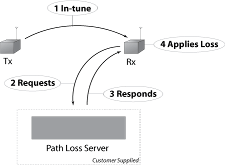
In Studio, simulated radios communicate when they are in tune and in range. Path loss effects are used to simulate radio degradation due to weather effects, terrain, and the time of day, among other factors. The radio receiver finds in-tune radios and sends out a protocol data unit (PDU) request to the server for each in-tune radio pair. The server returns a response packet, and the radio applies the path loss to the receiving radio’s audio quality.
The path loss interface feature is a separately purchased software option. In the Telestra web interface, the Path Loss Interface software option displays on Licensing > Licenses:

The path loss interface generally operates as follows:
ASTi uses a packet format similar to Distributed Interactive Simulation (DIS):
  RXpathPDU = record
     PDUheader     	: record
     			ProtocolVer   	: byte;
    	 		ExerciseID    	: byte;
     			PDUtype       	: byte;
     			PDUfamily     	: byte;
     			TimeStamp     	: Unsigned_32bit;
    			Length        	: Unsigned_16bit;
     			Pad1          	: Unsigned_16bit;
   		end;
    RXEntityID   	: record
     			Site   			: Unsigned_16bit;
     			Application/Host   	: Unsigned_16bit;
     			Entity     		: Unsigned_16bit;
       		end;
    RXDeviceID   	: Unsigned_16bit;
    TXEntityID   	: record
     			Site   			: Unsigned_16bit;
     			Application/Host   	: Unsigned_16bit;
     			Entity     		: Unsigned_16bit;
       		end;
    TXDeviceID   	: Unsigned_16bit;
    PathFactor   	: IEEE_float_32bit;
    LocationRX   	: record
     			X : IEEE_float_64bit;
     			Y : IEEE_float_64bit;
     			Z : IEEE_float_64bit;
       		end;
    LocationTX   	: record
     			X : IEEE_float_64bit;
     			Y : IEEE_float_64bit;
     			Z : IEEE_float_64bit;
       		end;
    FrequencyMSW : Unsigned_32bit;
    FrequencyLSW : Unsigned_32bit;
  end;
The radio receiver notifies the Telestra server to generate and send a Path Loss PDU, which delivers all PDUs in network-byte order (i.e., Big Endian). Path factor values range from 0.0–1.0, where 1.0 indicates no loss (i.e., 0 dB loss, 100 percent signal reception), and 0.0 indicates complete loss (i.e., -300 dB loss, 0 percent signal reception).
If the path loss interface and the host interface share the same Ethernet interface (e.g., eth0), set the port numbers to different values.
The radio receiver sends a Path Loss PDU packet to the host address and port number in the DIS Gateway. When the host server receives a packet containing path loss PDUs, it performs the following operations:
The reply packet must contain all the ID numbers in the original request packet. The host should not modify any field, except as described above.
For example, the following is true for line-of-sight (LOS) occulting:
If the host is using a more sophisticated model that accounts for frequency, then the PDU provides the transmitter/receiver pair’s frequency in the project configuration.
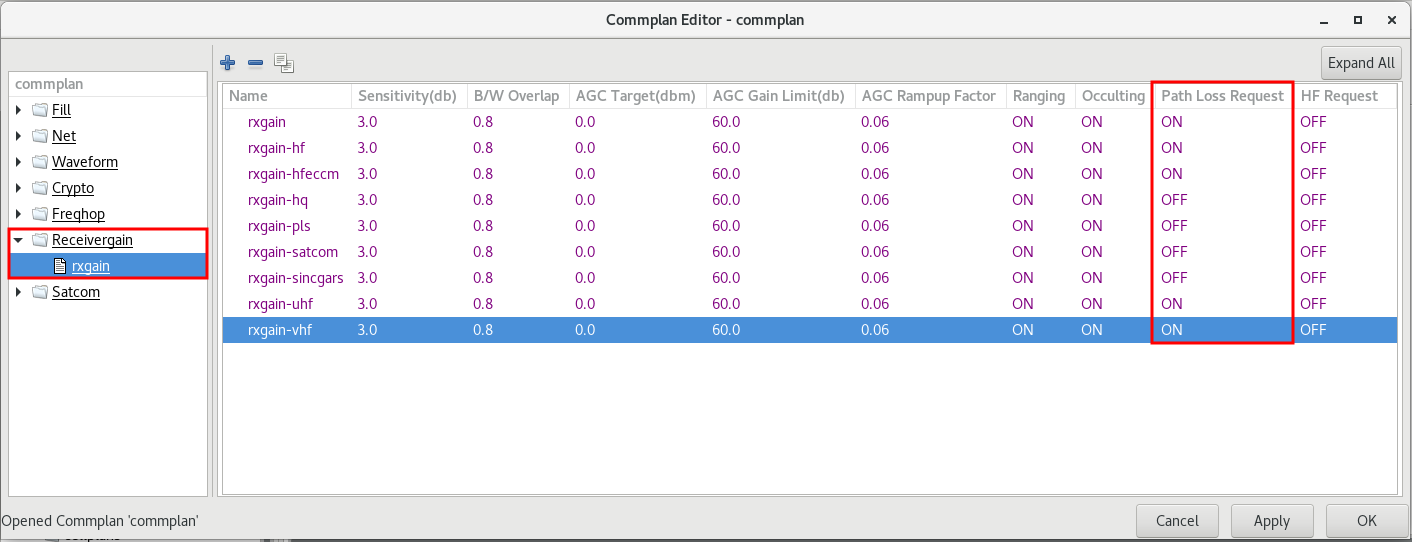
To enable the radio’s mode, waveform, and Rx gain combinations and ensure the radio issues the correct path loss requests, follow these steps:
 and
and  ...
...
 .
.
The path loss interface includes a set of parameters that determine when a radio should send a path loss request. These settings help control timeouts and default values. They also allow the radio to send path loss requests even if it’s located at the center of the Earth. You can set these parameters in the Domain’s parameters.ini file.
Similar to a radio’s normal timeout, the Path Periodic Timeout occurs when a radio has already received a path loss response and is stationary. The default value is 60,000 ms.
path_periodic_timeout = 60000
Similar to the radio’s moving timeout, the Path Moving Timeout occurs if either the transmitter or receiver are moving. If the path moving timeout occurs, the receiver sends a new request. The default value is 2000 ms.
path_moving_timeout = 2000
If the transmitter or the receiver move more than the Path Moving Threshold before the Path Moving Timeout, the receiver sends a new path loss request. The default value is 500 m.
path_moving_threshold = 500
The Path Request Timeout is the amount of time the receiver waits before sending another request. If the receiver sends a path loss request after meeting any of the above timeouts or thresholds, it uses this timeout until hearing back from the server. The default value is 2500 ms.
path_request_timeout = 2500
The Path Timeout Count is the number of Path Request Timeouts that must occur before the Path Timeout Factor.
path_timeout_count = 2
The Path Timeout Factor is the number the radio uses for path loss after reaching the Path Timeout Count. The default value of 1.0 produces the same result as if no path factor or additional attenuation existed.
path_timeout_factor = 1.0
The Path Initial Factor is the number the radio uses before it receives a response from the server. The default value of 0.0 produces the same result as a completely blocked path.
path_initial_factor = 0.0
The Path Force Request allows radios that are in tune with a transmitter located at the center of the Earth to still send out path loss requests. The default value is 0. To enable, set the value to 1.
path_force_request = 0
If you encounter problems, run through the following troubleshooting steps:

From the Telestra server's command line, run the following command:
tcpdump -i X udp port NNNNN
where X is the Ethernet interface number and NNNNN is the port number (e.g., tcpdump -i eth0 udp port 55001).
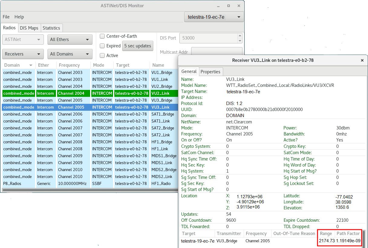
To check if your radio is using the path loss value in the Radio Monitor, follow these steps:
ASTi HLA configuration uses the DIS Gateway, as described in the HLA Installation Guide. However, HLA radios still require the Propagation Loss Interface for the receiver to properly send and receive path loss requests and responses. If you configure the Telestra to use HLA protocol for radio communications, set up the Propagation Loss Interface exactly as described above.
The Telestra-defined DIS radios and the DIS-like packet format both identify radios using four Studio Transceiver variables:
| Variable | Value |
| Site | Unsigned_16bit |
| Application/Host | unsigned_16bit |
| Entity | unsigned_16bit |
| DeviceID | unsigned_16bit |
Note: The Institute of Electrical and Electronics Engineers (IEEE) DIS standard refers to the DeviceID as the Radio Number.
In HLA, the object model (OM) defines the unique radio identifier. ASTi supports two primary OMs for radios: the ASTi Simulation Object Model (SOM) and Real-time Platform Reference (RPR) Federation Object Model (FOM). The ASTi HLA mapping file defines how the above data correlates to HLA objects/attributes and HLA interactions/parameters via the StreamTag attribute and/or parameter. Because the host computer and ASTi radio environment both recognize the above variables, they handle path loss requests and responses the same way. To learn more about HLA mapping files, go to “External FED/FDD, RID, and mapping files” in the HLA Installation Guide.