
This tutorial demonstrates the use of intercoms by creating a model with two operators operating on four busses using a PTT switch with the CommPanel component. The basic concept of the CommPanel is the connection of an operator input (usually a microphone, often via a Vox component) through a PTT gate and gain stage with an optional control input and scaling factor via a control selector switch to an intercom channel (bi-directional) provided by the Intercom Service. The intercom channel may be connected to various other component types to provide connectivity to other audio components or may simply be used as a basic intercom to provide standard intercom voice communications.
A simple example using the intercom bus includes two operators each with a 4-channel PTT switch. When both operators are on the same channel (intercom bus) they can communicate and listen to the same audio. Each operators needs their own CommPanel component.

In Studio, add a new Project, Layout, Load, and Sim model to create the canvas for building the model.
In the model canvas, add a new folder and name it 'Op1.'
In the folder, add a CommPanel > CommPanel4 and name it 'Op1_Panel.'
Then add an IOInterface > ACUchannel and name it 'Op1_ACUchannel.'
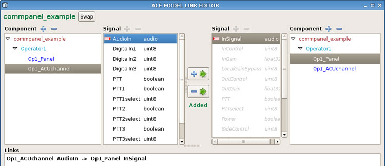
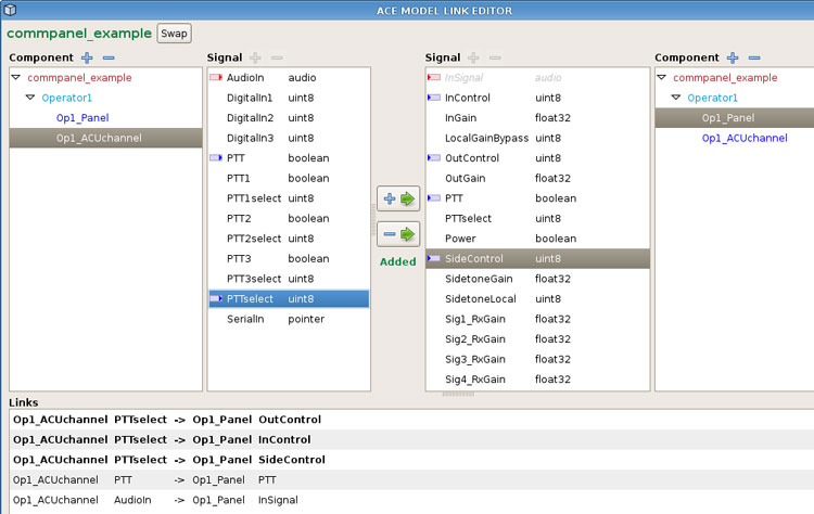
Create a link to route the audio in from the headset microphone to the 'Op1_Panel' (CommPanel), select the 'Op1_ACUchannel' AudioIn signal and link it to the 'OP1_Panel' through the InSignal.
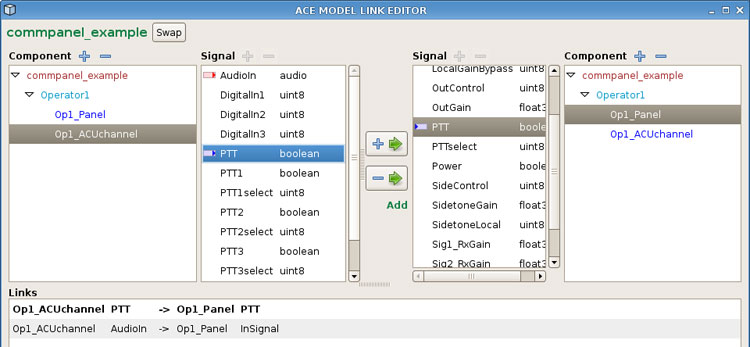
Create a link to route the audio in from the ACU to the 'Op1_Panel' (CommPanel) using the PTT, select the 'Op1_ACUchannel' PTT boolean signal and link it to the 'Op1_Panel' through the PTT boolean signal.
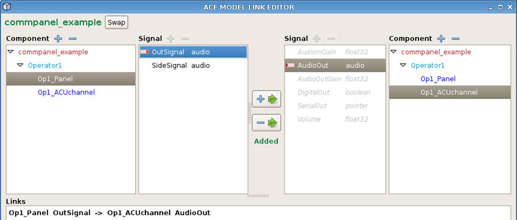
Create a link to route the audio out of the headset. Select the 'Op1_Panel' OutSignal and link it to the 'Op1_ACUchannel' through the AudioOut signal.
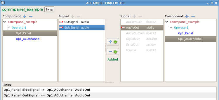
Create a link to route the sidetone of the headset back into the headset. This allows you to hear yourself through the headset. Select the 'Op1_Panel' SideSignal and link it to the 'Op1_ACUchannel' through the AudioOut signal.
Create three links for the PTT knob selection control. Select the 'Op1_ACUchannel' PTTselect and link it to the 'Op1_Panel' OutControl, InControl, and SideControl.
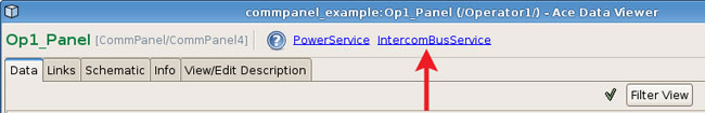
In the 'Op1_Panel' open the Intercom Bus Service.
In the Intercom Bus Service, add four new buses and name them.
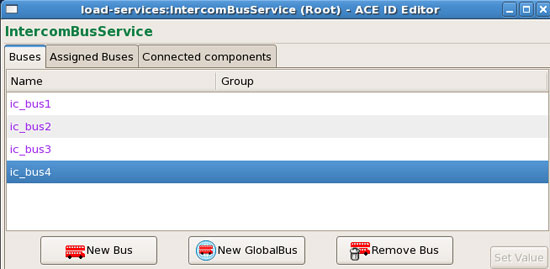
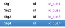
Navigate back to the 'Op1_Panel' and assign signal 1-4 to the busses by double-clicking in the value column. In the Intercom Bus Service, select a bus and then select the 'Set Value' button.
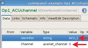
Open the 'Op1_ACUchannel' and assign the identifier and channel.
Copy and paste the 'Op1' folder and name it 'Op2' folder.
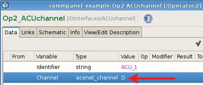
In the 'Op2' folder, change the component names to 'Op2' and change the ACU channel to a different channel that has a connected PTT and headset.
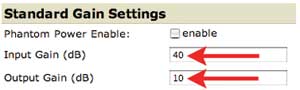
Verify the ACU channel gains set in the Telestra web interface, these will vary depending on ACU firmware.
In the load viewer select 'Reload.' Apply the changes.
Two users should be able to talk to each other through all four channel selections on the PTTs.