
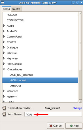
Right-click in the model canvas to add an item, under IOInterfaces select ACUchannel and name it ACU1. Then select the 'Add' button.
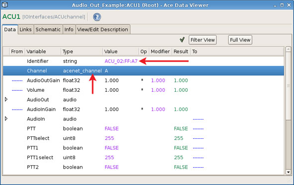
Double-click the ACU1 icon to open the Data Viewer for the component.
In the Identifier row under the Value column, double-click and type in the ACU specific name.
Note: By default, each ACU comes with a unique name, the user can change this name in Telestra web interface. To view the names of all ACUs on the network, navigate to the RMS Network > ACU screen.
In the Channel row select Channel A.
The Sine_Wave1 and ACU1 must be linked together to route audio out. To connect Sine_Wave1 to ACU1, middle-click on the Sine_Wave1 which will open the Link Editor.
To link the signal, select the Sine_Wave1 with the OutSignal to ACU1 with the AudioOut signal, as shown below.
Note: The signal options will appear after selecting each component.
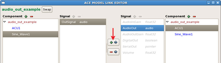
Click the plus symbol (+) button to create the link.
Save the Load.
Connect a headset to channel A of the ACU and listen to the sine wave.