
The objective of this note is to define an approach to the connection of the Host computer and the DACS. The DACS provides a TCP/IP Ethernet interface or Bit3 reflective memory interface. Either of these interfaces is applicable to the approach defined.
An Overview
The Ethernet buffer from the Host is typically constructed as booleans, integers, long integers, floats and ASCII text. With each type being an array of what is set to each element in the Host, for example:
Ada: Host_To_DACS.Booleans (I_Intercomm_Enable) : =TRUE;
Fortran: Host_To_DACS_Booleans (I_Intercom_Enable) =TRUE
This approach allows the easy addition of new variables and allows for quicker integration with the DACS. This is due to all of the variables being "close" to each other. If a tool or symbolic debugger is used, the host variable is displayed and manipulated, and then checked at the DACS. When hardware is integrated the switch can be toggled and the knobs turned, with the corresponding variable display at both the Host monitor and the DACS.
Once the Host interface is available to the DACS, the integration can start in earnest. The decision to wait for the hardware interface is many times determined by the project schedule. An earlier start on the Host/DACS integration will prevent it from getting into the critical path. Therefore, this note will discuss the integration effort without hardware (comm panels, etc.). The extra effort to integrate with the hardware is best accomplished after the Hardware Engineer is done testing with the VMIC (I/O system) in a stand-alone mode.
After the DACS' IP Address is determined, the default configuration file can be edited to set the address. The Host table (UNIX System) must be set to identify the DACS. If only one host is needed, the Host IP address may be omitted and the DACS allowed to track the Host. The User Data Protocol (UDP) provides one of the layers of the protocol stack. It is defined by the software engineer in the Host interface code and at the DACS. The UDP port number must agree with the Host. With the Host present and active (the interface software cycling), the Host Interface provides the data. However, if the Host is inactive, the "Initial Value" is used for the DACS' variables. A good use of this capability is to set the Intercom to default operation to all mics hot and all headsets on. This allows the DACS to provide a maintenance intercom function when the Host is not cycling or otherwise unavailable.
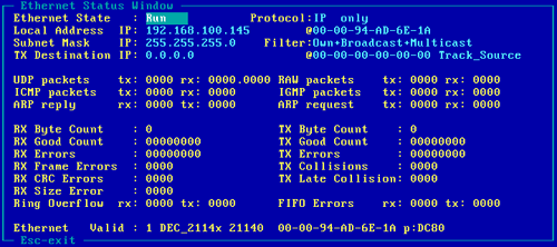
Figure 1 shows the Ethernet Status Window. When the Host is cycling the Host IP Address is filled in with the value from the actual messages on the Ethernet bus. This window also indicates other data relating to the protocols. It also provides the statistics of the buffers received/transmitted.

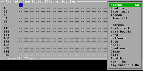
The receive data packet display window converts the received data to human-readable form. Figure 2 shows the data and F2 Menu. The various formats allow particular data to be observed. For each of the types from the Host, booleans, integers, floating point numbers, and ASCII text, there is an appropriate item of the F2 menu.

This display can be used to "connect" all of the variables. The procedure defined in the following pages uses the Window and Host monitoring.
The "connect" procedure defines a step-by-step procedure to make each variable available to/from the Host and DACS. A connect can be thought of as a wire connected from its source to its destination. Similarly, the Host variable must be connected to the DACS variable and vice versa.
The steps are:
The Intercom_Enable is determined in the Host by the Intercom Circuit Breaker (CB) on the overhead panel. When the CB is operated (and no other malfunctions are active), the enable will change state. The offset, 27, was observed from the receive data packet display (see figure 2). The procedure is repeated for each variable, until all Host to DACS variables are connected.
The connect from the DACS to the Host is a similar effort.
It is recommended that the end-to-end connect of the DACS be accomplished after the simulator hardware is available. If not, the units, word sizes, and buffer locations may change. The goal should be to have the DACS model, Host Interface and hardware available for integration and test.