DACS App Note
RIU (Version C & later) Digital Outputs: Driving LED, ext. relay or working with AIU (#17b)
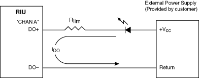
Application 1: Driving an External LED Using RIU Digital Outputs
Note: Applies to RIU version C and later (indicated by part number: RIU-x-C) only.
Notes
- RIU DOs can be directly connected to loads (as shown). RIU DOs can also be connected to a load through the DO jack of an Audio Interface Unit (AIU). The connection through the AIU is passive. Connecting the load to an AIU can simplify cabling configurations. Application 3 below shows how to connect an RIU DO to a load through an AIU.
- Typical Digital Output circuit is depicted. See Parts 4 & 5 below for RIU and AIU pin assignments.
Digital Outputs are optically isolated solid state switches.
- Current through each DO circuit must not exceed 75 mA.
Specifications
- Vcc (max) = +30 VDC
- Vcc (min) = +3 VDC
- IDO (max) = 75 mA
- Rlim (minimum value) = (Vcc - 1.7)/0.075
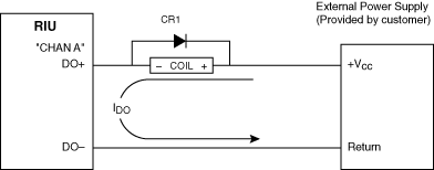
Application 2: RIU Digital Outputs. Driving external relays, RIU only (no AIU).
Note: Applies to RIU version C and later (indicated by part number: RIU-x-C) only.
Notes
- Typical DO circuit is depicted. See Parts 4 & 5 below for RIU and AIU pin assignments.
- DOs are optically isolated solid state switches.
- Current through each DO circuit must not exceed 75 mA. The resistance of the relay coil is critical (see Specifications).
- Protective diode CR1 is necessary. Select a relay with an internal protective diode or use a discrete diode, 1N4001 or equivalent. Failure to use a protective diode may result in damage to the RIU.
Specifications
- Vcc (max) = +30 VDC
- Vcc (min) = +3 VDC
- IDO (max) = 75 mA
- RCOIL (minimum value) = (Vcc - 1.7)/0.075
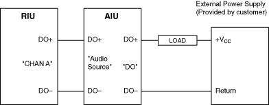
Application 3: RIU Digital Outputs. Connecting RIU DOs through an AIU.
Note: Applies to RIU version C and later (indicated by part number: RIU-x-C) only.
Notes
- Typical DO circuit is depicted. See Parts 4 & 5 for pin assignments.
- DO circuits are passively routed through the AIU.
- Current through each DO circuit must not exceed 75 mA. The load resistance is critical (see Specifications).
Specifications
- Vcc (max) = +30 VDC
- Vcc (min) = +3 VDC
- IDO (max) = 75 mA
- RLOAD (minimum value) = (Vcc - 1)/0.075
Part 4: AIU pin assignments
Note: Applies to RIU version C and later (indicated by part number: RIU-x-C) only.
Audio Interface Unit
"Audio Source" Jack
Audio Interface Port, with Digital Interface
Connector Type: DB9 female

Front View
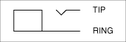
Audio Interface Unit
"DO" Jack
Digital Output Port
Connector Type: 3.5mm, 2 Cond., female
| Signal Description |
AIU Panel
"Audio Source" |
AIU Panel
"DO" |
| Digital Output + |
1 |
Tip |
| Digital Output - |
6 |
Ring |
Part 5: RIU pin assignments
Note: Applies to RIU version C and later (indicated by part number: RIU-x-C) only.
Remote Interface Unit
"CHAN [A,B,C,D]" Jack
Audio / Interface Port, with Digital Interface
Connector Type: DB9 female, typical
Front View
| Signal Description |
RIU Panel
"CHAN [A,B,C,D]" |
| Digital Output + |
1 |
| Digital Output - |
6 |