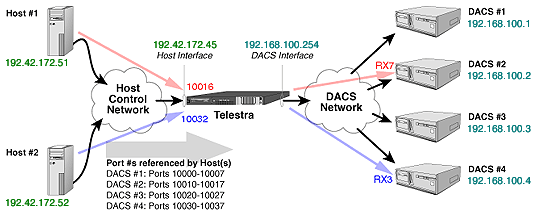

Host control via Telestra is implemented through a third Ethernet port on the Telestra unit that serves as a host interface. This port replaces the host interface port on the DACS so that Telestra now receives all inputs from the external network. Use of this port as a host control interface requires Telestra version 1.4 or higher and Model Builder version 4.06 or higher. This application note addresses how Telestra, the host computer, and the DACS should be configured for host control via Telestra to function properly.
The following instructions describe the setup procedures required to ensure that data generated from a particular host computer are passed to the intended DACS and vice versa. Note that there are many possible combinations of host computers and DACS systems that may be interfaced via Telestra. This application note does not attempt to list or define all possible combinations.
The basic concept to understand is that Telestra functions as a routing mechanism for data packets. Telestra simply resides between the host computer and the DACS and maps a source IP address of an incoming packet to a destination IP address on an outgoing packet. Telestra does not respond or modify the data that passes through it.
A maximum of four DACS may connect to a single Telestra unit. Telestra receives data from a host computer and routes that data to the intended DACS according to user-supplied data. The user specifies which host computer controls which DACS through the Telestra Configuration Utility. The following instructions describe how the user assigns a DACS to a host computer to provide a routing path for Telestra.
Note: The following instructions are version-specific.
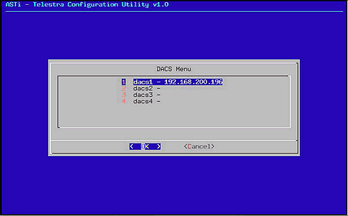
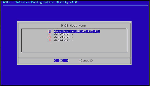
The Telestra Configuration Utility modifies several configuration files within Telestra based on inputs from the user into the utility. These inputs are written to the files when the user saves their changes upon exiting the utility and loaded into Telestra when the system is rebooted.
The Telestra Configuration Utility thus provides a convenient method to access the multiple Telestra configuration files from a single interface so that the user does not have to remember the paths to and names of the individual files.
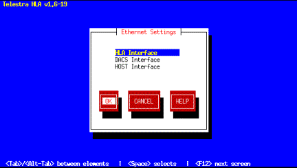
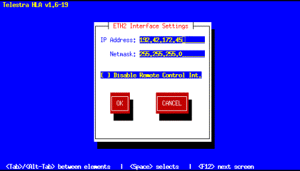
From the Ethernet Settings Menu, choose the "
Note: The HLA and DACS Interfaces should also be set to valid values. More information about these interfaces may be found in the Telestra 1.6 User Guide.
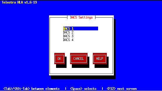
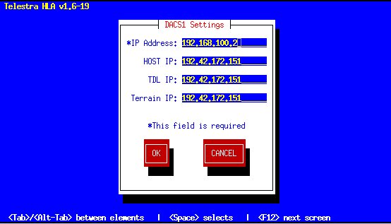
Set the "Host IP" field to the IP address of the host computer that will control DACS1. This must be on the same netowrk as the Telestra Host Interface that was configured in Step 8.
Note: The "IP Address" value is the IP address of DACS1.
The Telestra services are restarted automatically upon exiting the utility. The Telestra Configuration Utility modifies the configuration file based on inputs from the user into the utility. These inputs are written to the files when the user saves their changes upon exiting the utility and loaded into Telestra when the system is restarted.
In Telestra versions 2.0 and later, the ASTi HLA Communications software is integrated with the Telestra web interface. The Telestra web interface is a specialized web server that provides complete sight and control of all ASTi devices on the simulation network. Host control parameters for the DACS are configured using a standard web browser from anywhere on the network.
Please refer to the ASTi Telestra v2.x User Guide for instructions on how to configure the Telestra system and DACS host IP addresses.
The Telestra host interface, like the DACS host interface, receives data from the host computer as Ethernet packets. Each packet includes an Ethernet header, an Internet Protocol (IP) header, and a User Datagram Protocol (UDP) header. The UDP header contains two fields that define the transmitter port and receiver port. These port addresses denote the software application or "service" within the device which is the source of, or the destination for, the data packet.
The host computer sends data to the IP address of the Telestra host interface and the UDP port address of the specific port on the DACS. The port addresses that the host references use the following format:
100XY
... where X--which ranges from 0 to 3--indicates to which DACS the data is addressed, and Y--which ranges from 0 to 7--indicates the UDP port on the DACS that will receive the data. The port addresses referenced by the host are shown explicitly in the example figure below.
Note: The X value corresponds to the DACS slot number used in the Telestra Configuration Utility as follows:
X = 0 for DACS #1
X = 1 for DACS #2
X = 2 for DACS #3
X = 3 for DACS #4
Telestra routes return packets it receives from the DACS to the IP address of the corresponding host on a specific port number. The port addresses at which the host receives data from Telestra use the following format:
100X0
... where X--which ranges from 0 to 3--indicates which DACS sent the data. For example, if Telestra receives a packet from DACS #3, it will forward it to the host assigned to DACS #3 on port 10020. This scheme allows a single host to receive data from multiple DACS on separate ports.
The DACS receives values for host controlled parameters on one of eight receiver ports, which are identified as RX1-RX8. Each receiver port has a unique UDP port address internal to the DACS. The port address assignments are as follows:
RX1 = 10000
RX2 = 10001
RX3 = 10002
RX4 = 10003
RX5 = 10004
RX6 = 10005
RX7 = 10006
RX8 = 10007
The DACS transmits packets to the host on its transmit port whose UDP address is 10000. The port addresses of the transmit and received ports are displayed in the Ethernet Control window. Please refer to the Model Builder Reference Manual for more information about this window.
Note: The port address displayed in the Ethernet Control Window on the DACS #2-#4 will not match the port addresses referenced by the host. This is because Telestra performs a conversion that drops the 'X' value and results in a basic IP/UDP address pairing.
Return packets from each DACS are sent to the IP address of the DACS interface on the Telestra unit. The destination IP address in the DACS is automatically set to the IP address of the Telestra DACS interface. These packets are then routed to the corresponding host IP address as defined in the configuration utility on the correct port number as described above.
For the case in which the DACS using Telestra has two Ethernet ports, an additional step is required. In the DACS configuration file, the following line should be added:
ethernet = 1
This command will ensure that the DACS is communicating with the Telestra unit through the correct Ethernet port.
The figure below shows an example in which two host computers control four DACS units through Telestra. In this example, the Telestra Configuration Utility has been configured as follows:
DACS1 Settings
IP Address: 192.168.100.1
Host IP: 192.42.172.51
DACS2 Settings
IP Address: 192.168.100.2
Host IP: 192.42.172.51
DACS3 Settings
IP Address: 192.168.100.3
Host IP: 192.42.172.52
DACS4 Settings
IP Address: 192.168.100.4
Host IP: 192.42.172.52
Telestra Ethernet Settings
Host: 192.42.172.45
DACS: 192.168.100.254
Data from Host #1 intended for RX7 on DACS #2 would be addressed to the Telestra host interface IP address on port 10016. Data from Host #2 intended for RX3 on DACS #4 would be addressed to port 10032.
Note: Even though the Host #1 sends packets to port 10016, the port address for RX7 on DACS #2 would still appear as 10006 in the Ethernet Control window. Likewise, Host #2 sends packets to port 10032, but the port address for RX3 on DACS #4 would appear as 10003.
