

ASTi's product name, "Telestra", refers to the Linux-based platform on which a number of applications can be run. These include the Telestra web interface software, HLA communications software, and various radio simulation servers.
At this time, there are a variety of software combinations that can run on a Telestra platform.
The main distinction between different software versions is:
Regardless of the application(s) running on a Telestra system, each platform supports three (3) ethernet interfaces. This application note attempts to clarify the sometimes-confusing issues involved with integrating a Telestra system with your existing network architecture.
Every Telestra platform ships with default settings for each network interface:
| Interface | Default IP Address | Default Subnet Mask |
|---|---|---|
| eth0 | via DHCP or 0.0.0.0 | via DHCP or none |
| eth1 | 192.168.100.254 | 255.255.255.0 |
| eth2 | 20.1.1.1 | 255.0.0.0 |
For more information about out-of-the-box configuration, please consult the "Initial Network Configuration" section of the Telestra User Guide for your version of Telestra software.
As technology evolves, the Telestra chassis (and the locations of the three ethernet interfaces) will continue to change. Each ethernet port will be labeled on the rear of the Telestra chassis upon shipment from ASTi.
In example diagrams throughout this application note, Telestra servers will be represented by either of the figures below.


Regardless of your software version, any two ethernet interfaces on your Telestra system MUST NOT be configured to share the same network segment. Meaning: each ethernet interface must have its own IP address and subnet mask such that its network configuration does not overlap at all with the others.
Sections II-A and II-B do not address HLA-specific configuration rules; please see section II-C.
Again, any two ethernet interfaces on your Telestra system MUST NOT be configured to share the same network segment.
Telestra web interface provides remote DACS management over the network, via its web-based interface. Users access the Telestra web interface and its management capabilities using a standard PC with a web browser.
For all 3 network interfaces:
The diagram below represents the Telestra web interface's standard (and DIS) network configuration. Note that the DACS systems to be managed by the Telestra web interface are on the same network segment as Telestra eth0. In this example, the Browser PC is also on the same network segment. Simply point the web browser to the IP address of Telestra eth0 to access the Telestra web interface.
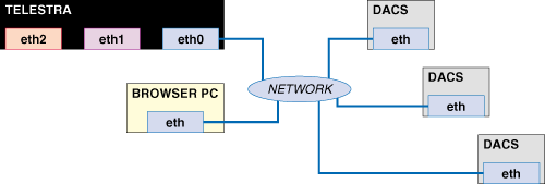
This is the recommended network configuration for Telestra web interface on a standard or DIS network.
WHY?
After initial installation or cold start of the Telestra system, you should change the system's IP address to match your local network using the Telestra Configuration Utility. This utility allows you to change the settings of eth0 only. (This procedure is outlined in the Telestra User Guide, so will not be covered here.)
Also--at this time--the Telestra server only publishes the IP address of eth0 to other Telestra servers during the Auto-Discovery process (where each Telestra server locates all others on the network).
It is possible to stray from this recommended network configuration without adversely affecting the operation of DACS or Telestra systems, but this requires more work on your part, as we'll soon see.
The diagram below represents an alternative to the recommended network configuration, outlined above.
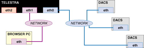
This network configuration will work, but is not recommended.
WHY NOT?
First, it takes longer to set up. You'll have to use the Telestra Configuration Utility to change Telestra's eth0 IP address, wait for a system reboot, point to eth0 with a browser on the same network segment (blue in diagram), change Telestra's eth1 IP address through the Telestra web interface, wait for a network services restart, then point to eth1 with a different browser on the other network segment (purple in diagram).
Also, because the Telestra web interface only publishes the IP address for the system's eth0 interface, it may become confusing to have to point the browser to an entirely different IP address (that of eth1).
This example is only included to demonstrate proof-of-concept: the Browser PC can be on a different network segment than managed DACS systems, provided two of Telestra's ethernet interfaces are also members of those networks.
If, for some reason, your application requires the Browser PC to be on a different network than the DIS network, a configuration like the one pictured below will avoid confusion and your having to do more work, but will still conform to your network architecture.
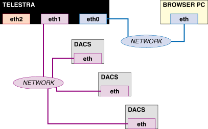
The diagram below represents yet another alternative to the recommended network configuration, outlined in section A above.
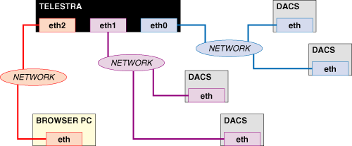
This network configuration will work, but is not recommended.
WHY NOT?
For the same reasons listed in section B above, namely longer set up time and the possibility of confusion.
This example is only included to demonstrate proof-of-concept: multiple, managed DACS systems can be on separate network segments, provided two of Telestra's ethernet interfaces are also members of those networks.
Again, if your application requires three separate networks, something like the setup pictured below will do the trick and minimize hassles.
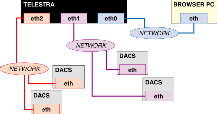
Although the network setup shown in section 1 is the recommended configuration, your particular application may require a setup similar to that shown in section 2 or in section 3. In all of the examples above, the Telestra server can locate and manage all of the DACS systems shown, and you should not experience any difficulty accessing the Telestra server itself.
AS A RULE: Always try to have your Browser PC on the same network segment as Telestra's interface eth0.
Using the Telestra web interface to manage DACS systems on multiple networks requires special consideration. The most important thing to remember is that, unlike closed LANs, cases like these require "gateway" settings for each network interface.
The diagram below shows this concept in its simplest form.
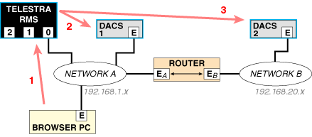
To make this work, you must employ a router, and set up the systems to use it. For this example, we've assigned arbitrary class C networks for both networks A (192.168.1.x) and B (192.168.20.x). The following settings are arbitrary as well, but demonstrate a few important points.
| Interface | IP | Netmask | Gateway | Managed By |
|---|---|---|---|---|
| Telestra eth0 | 192.168.1.1 | 255.255.255.0 | 192.168.1.100 | n/a |
| DACS 1 | 192.168.1.2 | 255.255.255.0 | 192.168.1.100 | 192.168.1.1 |
| Browser PC | 192.168.1.3 | 255.255.255.0 | 192.168.1.100 | n/a |
| Router EA | 192.168.1.100 | 255.255.255.0 | n/a | n/a |
| Router EB | 192.168.20.50 | 255.255.255.0 | n/a | n/a |
| DACS 2 | 192.168.20.1 | 255.255.255.0 | 192.168.20.50 | 192.168.1.1 |
Although this example is quite simple, the same concepts apply to multiple groups of DACS systems on any number of separate--but interconnected--networks. Configure gateways locally, point the Telestra servers to DACS systems over the WAN, and vice versa.
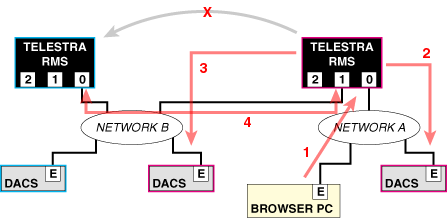
Employing multiple Telestra servers to manage a number of DACS systems may be required by your application. In this section, we'll look at a very simple example using 2 Telestra servers that works just fine. Then, we'll introduce a couple of GOTCHA!'s that the use of multiple Telestra servers presents, and how to avoid them. First, the most basic example:
First, the most basic example:
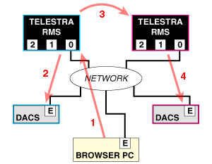
Jumping from one Telestra server to another (step 3 above) is made possible through a Telestra web interface feature called "Auto-Discovery". Each Telestra server pumps out a "heartbeat" once every 5 seconds that contains various information about the server itself, including the IP address of its eth0 interface. Every other Telestra server that can receive that information will display a neat little Telestra server icon in your web browser that you can click on. At that point, your browser leaves the original Telestra server, and begins retrieving information from the other one. This is bi-directional, meaning you can jump back-and-forth between Telestra servers at will.
Here, we have almost the exact same network configuration as in the prior example. The only difference is that our second Telestra server's connection to the network is via a different interface (eth1). Take a look:
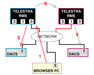
In this example, you can still hit the first Telestra server with your browser, and manage its associated DACS system. You cannot, however, jump from the first Telestra server to the second one; therefore, you can't manage the other DACS system.
WHY NOT?
It's a limitation of the Auto-Discovery process. Each Telestra server pumps out the "heartbeat" on all its interfaces (eth0, eth1 and eth2). But each Telestra server only publishes the IP address of its eth0 interface in the "heartbeat".
The first Telestra server receives the second's "heartbeat", so it displays the cool little icon in your browser. BUT, the link it creates so you can click on the icon points to the IP address of the second Telestra server's eth0 interface. As you can see, we don't have anything connected to the second server's eth0; it's not "on the network", and your browser will be unable to access its web server.
HOW TO AVOID THIS PROBLEM
Point your browser to the IP address of the second server's eth1 interface, provided you know what it is. Then, you can manage the other DACS.
OR, better yet...
In sections 2 and 3 above, we demonstrated that the Browser PC and managed DACS systems don't have to be on the same subnet, nor do they have to be connected to a Telestra server using its same network interface. This also applies to Telestra servers, but can present problems.
In this example, point the web browser to the local Telestra server to manage one DACS on our LAN, and another DACS over the WAN. Even though both Telestra servers will know about the other (and display this information to you), you cannot however, jump from our local Telestra server to the remote Telestra server.
WHY NOT?
You can't do this because, basically, neither Telestra nor the Telestra software is a network router. It is important to understand the flow of data and the idea of "network segments" in this example. Let's break it down:
The key is... in all of these paths of communication, the two communicating devices are both members of the same network.
From the local Telestra server's viewpoint, some information is coming in from Network A via eth0, and some is coming in from Network B via eth1. The Telestra software doesn't care where the information is coming from; it has the info, and will give it to you upon request.
In order to jump from the local Telestra server to the remote Telestra server, the network traffic involved would have to travel into local Telestra eth0, out of local Telestra eth1, and into remote Telestra eth0... and then all the way back. Take a look:
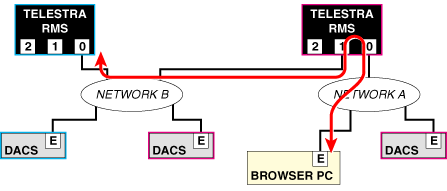
This will not work because 1) you're dealing with two separate network segments, and 2) Telestra will not pass HTTP (web protocol) traffic in one network interface and out the other, or vice versa.
So how do you get to that remote Telestra server?
Install a router:
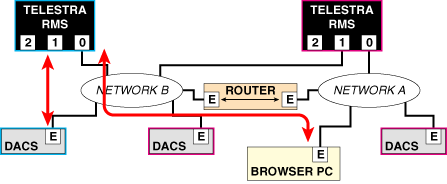
Telestra's multicast routing software is controlled via the Telestra web interface and works in conjunction with Model Builder software running on DACS systems (which may or may not be managed by the Telestra, your call).
Using the Telestra platform as your multicast router allows you to: 1) route desired transmissions directly to specific receivers, 2) exclude others from receiving that transmission, and 3) restrict local traffic to the local subnet, and away from the wide area network. This translates into dramatic improvement in your network's efficiency. See ASTi's discussion, "ASTi's Enhanced IP Multicasting Improves Internetwork Efficiency" for more information and a great sales pitch.
Because of its nature, Telestra as a multicast router only controls traffic between network interfaces eth0 and eth1. To maximize its effect as such, it only makes sense to keep your DACS systems segregated from the rest of your simulation network. Otherwise, how can the router do its job?
The diagram below shows the recommended location of DACS systems for optimal network performance. Note the various locations of Browser PCs and their labels.
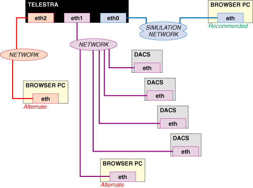
DACS: Create a DACS subnet that connects with Telestra's eth1, and configure the systems to use multicast. The Telestra's multicast router will only allow "subscribed-to" network traffic to pass through to eth0, and onto the simulation network. For more information regarding DACS system configuration, please see Application Note 41: Multicast Routing for Voice Networks.
Browser PCs: The Browser PC sharing a network with Telestra's eth0 is the recommended location from which to access the Telestra server. Networking the Browser PC at either of the alternate locations will work just fine, but translates into more work for you.
Because of the software's inherent functionality, Telestra HLA systems require a fixed network architecture.
The diagram below shows the only valid network configuration for Telestra HLA systems.
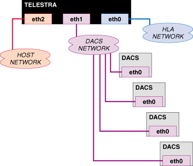
To access the Telestra web interface, you can connect a browser PC to any of the three networks shown above.
Recommended: Connect the browser PC to the HLA Network (eth0).
For information regarding port numbers used by Telestra HLA, please see Application Note 44: Host Control Via Telestra, and the Telestra User Guide.
There are no "hard-and-fast" rules for configuring Telestra 3-series software network parameters. The radio, terrain & Telestra servers will accept and reply to requests on any of the three ethernet interfaces.
However, please pay attention to these suggestions from the 2-series section of this document:
When setting up the system to work with a host computer (e.g., for model manipulation), you must specify which interface to use--but this is also reconfigurable at any time.
Again, any two ethernet interfaces on your Telestra system MUST NOT be configured to share the same network segment.