
This application note covers the following:
Before describing what Jitter is and how to combat the effects of Jitter, it is useful to step back and take a quick look at the effects of fixed and variable delays with regards to voice communications. In voice communications across a LAN or WAN there are two main types of delays that are introduced:
The total end-to-end delay across the network is the sum of the fixed and variable delays at the various hops or interfaces. As a simple example the total end-to-end delay from one operator to another operator consists of the following main components:
Fixed Delays
Variable Delays
With our two-operator example, we will first need to convert operator one's microphone audio from an analog signal to a digital signal made up of 1s and 0s. Next that digital signal will have some delay associated with the operator modeling and the platform the operator is using (DACS, T3, Telestra, etc). The specific system configuration and technology will dictate what exactly the delay will consist of; however for the purposes of this discussion it is not that relevant. UDP packetization is the delay associated with filling a single UDP packet for transmission onto the network. It consists of the time required to create the packet header and fill in the voice data. This is often referred to as the Transmit Buffer size and for voice communications refers to the amount of audio you want to buffer up before sending a packet. The smaller the packet, the smaller the effect on overall latency. However, the smaller the packet, the higher the packet rate and CPU load. Small packets will also cause a reduction in the effective data throughput as the overhead associated with each packet will add unnecessary bandwidth onto the network.
In general you want to have a balance between the effects of latency and CPU/Network performance. Ethernet serialization is the delay associated with getting a packet from the NIC TX Buffer to the physical wire. Finally, LAN or WAN propagation effects are fixed delays associated with the transmission medium. With all things being equal, it will take more time to transmit a signal from the East Coast of the United States to the West Coast then it would to send a signal within a single state.
The variable delays introduced into the end-to-end transmission path are generally due to Egress Buffer queuing. For example, if we have a Telestra sending an Ethernet packet that packet may have to wait a small time before it is transmitted if there is another packet(s) already in the queue. This same effect is seen at each hop in the end-to-end communications path. See example diagram:
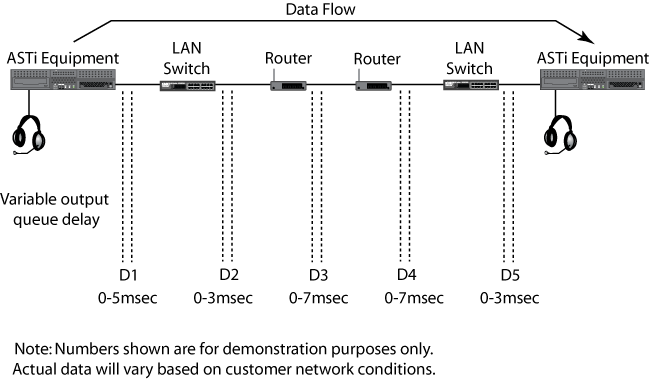
We have five places where variable delay is introduced. There is the egress interface on the ASTi equipment, two LAN switches and two routers. So the total variable delay is equal to D1 + D2 + D3 + D4 + D5. The total instantaneous packet delay variation or the delta between successive packets that is what is often referred to as Jitter. In voice communications, as speech is a Constant Bit Rate (CBR) service, jitter must be removed before the audio is processed.
As seen above, jitter is the sum total of instantaneous packet delay variation or delta between successive packets and is caused by egress buffer queuing along the communications path. Or put in plain English it is a measure of variability in packet delivery timing.
In a perfect world we would send packets at a nicely periodic rate (say one every 25mS) and on the receiving end see them arrive one every 25mS. However, in the real world we rarely have the luxury of a dedicated network and even if we did, as soon as we need to support more than one packet stream, we have the potential of congestion. The effect of congestion is to cause small delays in the delivery of packets from one end to the other. As more traffic is added to a network, the delays experienced will change and it is this variability in the delay time that is most often referred to as jitter.
For most data, the effect of jitter is not significant. For example, the delivery of a web page will really not suffer any ill effects when served up over a network with significant jitter - the page will ultimately appear, just as it would on a network with little or no jitter. However, the effect on audio signals is a little different.
As voice communications is a Constant Bit Rate service we need to ensure that all variable delays are accounted for in the end-to-end path. This is accomplished through the configuration of a receive/jitter buffer. Across the various ASTi products the specific name and units (Samples vs. msec for example) of the buffer will vary, however the core function of each is the same. That is to create a fixed delay buffer or jitter buffer that is equal to the worst-case variable delay in the network. With this in place, we are able to process audio communications as a CBR service without loss of data due to variable delays in the network path. This is all possible because we can hold the first sample for a period of time before beginning playback. Taking the above example and applying it to the configuration of a jitter buffer, we would start by adding up the worst-case delay associated with each buffer queue:
Worst Case Jitter Buffer = D1 + D2 + D3 + D4 + D5 = 25msec
Given some statistical variance in each queue delay it is unlikely that the worst-case scenario would occur. However, it is a good starting point for testing. If the jitter buffer configured is too small then large variations in delay can potentially cause the buffer to under-run. The effect is that you will get one buffers worth of null audio, which will likely be audible to the end user. However, if the jitter buffer is too large then it will have the downside effect of adding unnecessary latency to the end-to-end communication path. Additionally, the buffer depth will increase which may cause the buffer to over-run and will also cause a gap in the audio transmission, which would likely be audible to the end user.
All ASTi audio systems have configurable parameters that allow adjustment of the key parameters for network behavior, including jitter. The following information covers the configuration of these parameters for Distributed Interactive Simulation (DIS).
Note: The following instructions are for the latest version of Telestra (Telestra 4). For previous versions, please see Appendix A: Configuring Legacy Systems.
The parameters used by the radio sub-system are defined in the Domain Folder, within the current in-use Domain sub-folder (by default this will be called "domain").
Locate the file called "parameters.ini" and select "Edit File".
The receive delay is defined using a value under the [audio] section of the file and is called "holdoff". This is the amount of audio that must be received prior to beginning playback. So with a default of 25msec you must have received 25 or more msec worth of audio at which time playback will immediately occur. For example, with a default TX buffer of 20msec and hold-off of 25msec you will need to receive two full packets before starting playback. This has the net effect of providing a 20msec jitter buffer as two full packets must be received prior to playback. Edit the file, save the layout and re-install to cause the value to take effect.
The transmit buffer size currently is not an adjustable parameter within the "parameters.ini" file, but it can be temporarily changed from within the Telestra web interface pages, by selecting Health > ASTi Realtime > RCE > Parameters and locating the value called "Max Tx Audio Payload Milliseconds". The value is the buffer delay in milliseconds. Select the update link to the right and enter the desired value. This change will only persist until the layout is reinstalled. Future versions of Telestra will include this parameter within the domain parameters file, allowing permanent setting. By default this value is 20ms.
Using the default configuration values the Telestra provides a jitter buffer of 20msec.
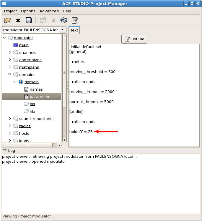
Domain > parameters.ini > holdoff
The exact jitter buffer value required to combat a poorly performing network is difficult to predict since it will be difficult to measure. However, since it is relatively easy to adjust the timing values on any version of ASTi communication system it should be relatively easy to experiment with values and find the minimum acceptable numbers that provide reasonable performance.
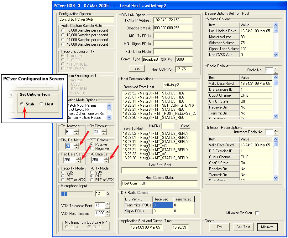
The parameters used to define the radio behavior may be set using the PC'ver GUI by selecting the "PC'ver Configuration" button. The "Configurations Options" window will display. Ensure that the "Set Options From Host" button is selected in the bottom right of the window.
The transmit buffer size is set independently for radios and intercom channels. Locate the "Rad Data Sz" data entry box for radios. By default the size is set to 250 samples (31.25ms). Intercoms are set using the "I/C Data Sz" value.
The received delay value is set using the "Play Del Ms" data entry box, and by default is set to 30ms.
Using the default configuration values PCVer provides a jitter buffer of 30msec.
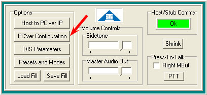
PC'ver GUI
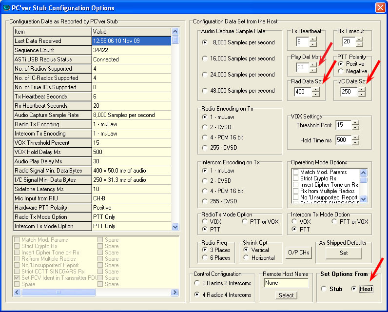
PC'ver Configurations Options
The PC'ver radio parameters discussed above can also be set in the PC'ver Stub as long as the "Set Options From" Stub is selected on the PC'ver Configuration screen.
PC'ver Stub
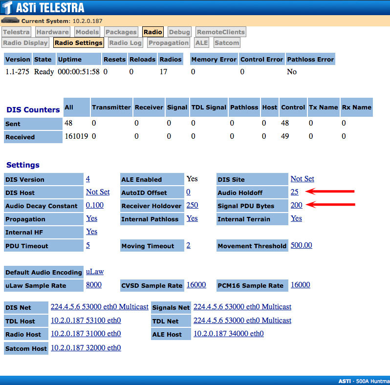
All parameters used by the network radios/intercoms are set using the Telestra web interface, under the Radio > Radio Settings tab. For general details about the Telestra 3 system, please see the Telestra 3 User Guide (DOC-01-TELS-UG-3).
The transmit buffer size used by the radio environment for DIS signal PDUs is defined on the Radio Settings page, and is set using the "Signal PDU Bytes" value. This defaults to 200 and is in units of bytes, which conveniently maps to a count in samples and equals 25ms.
The receive delay is defined on the same page under "Audio Holdoff" and defaults to 25 (units are in ms).
Using the default configuration values the Telestra 3 provides a jitter buffer of 25msec.
DIS > Rx Delay
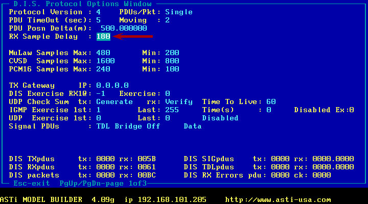
The transmit buffer size is defined in a configuration file parameter called DIS:Samples. By default the system uses a variable size buffer using the following limits:
minimum size = 200 samples
maximum size = 480 samples
which at 8kHz sample rate translates to 25-60ms. The command has the format:
DIS:Samples = <decimal number>[,decimal number]
where <decimal number> defines the minimum sample count in a packet, and [,decimal number] defines the maximum packet size. If <decimal number> alone is used then the sample count in a packet is fixed at the stated size. The minimum value for the number of samples is 32 and the maximum is 480.
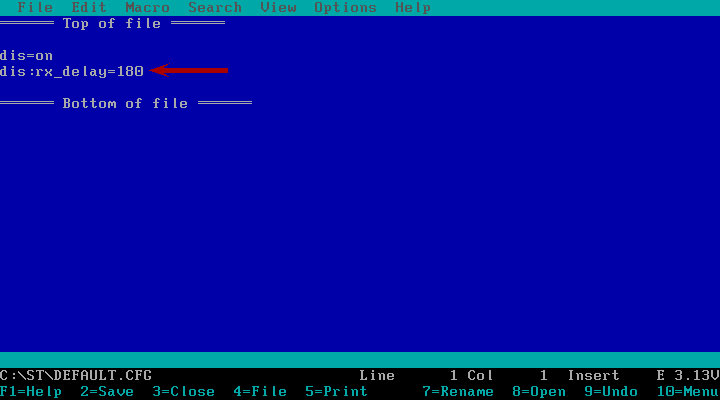
The receive buffer delay is set in another configuration file parameter called DIS:Rx_Delay. Again this is in units of samples and defines the time the system waits after receiving a PDU before starting to play audio. By default this value is set to 160 samples, or 20ms (at 8kHz sample rate). The command has the format:
DIS:Rx_Delay = <decimal number>
with the minimum valid number being 160 and the maximum being 800.
Using the default configuration values the DACS provides a jitter buffer of 20msec.
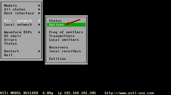
DIS Network > Options
DIS Network > Samples
DIS Network > Rx Delay