
Note: These are answers to actual questions fielded by ASTi over the course of product development and company growth. Some of the questions and answers here may have already been implemented in software/hardware solutions. Contact ASTi to verify.
If you receive an error message after upgrading to a newer version of Model Builder, and the error message appears when you install the software:
Reboot the system, and this message should go away. If the error message re-appears, try reinstalling the software, and rebooting again. This should eliminate the problem.
For positioning the radios you do, indeed, have several options. On the DACS, the world is modeled after the WGS84 specification (smooth round ellipsoid). Geocentric or geodetic world position objects are DIS-compatible.
Entity is for entity attachment. This is primarily targetted where there is a need to take a generic radio and "attach" it to a DIS entity.
HaveQuick features are not fully defined by the current DIS standard. There are implementations out there, but they are generally done in the lab. Our questions to you would be: What features over and above a standard radio do you actually need? Are these features required to be compatible with other platforms on the DIS network? If so, what are the other platforms you intend to operate with, and how do they currently handle the HaveQuick features?
As you can see, it is a question of what is necessary for training and, of course, interoperability. Because these features are not defined completely by the DIS standard, it becomes an issue of the requirements of the specific program.
An additional note - We have customers who have implemented a generic radio for the ARC-164 with the necessary beeps, anti-jam mode clicking and other cues. It may be that this is all that is required.
The general concept is that the DACS provides the Host computer with a list of in-tune radio transmitters and receivers (based on smooth round earth), their frequencies, and their locations (this includes DIS environment radios, not just local radios). This list is updated and provided on an ongoing basis. The Host computer is in charge of determining the signal, degradation which is inserted into the table and the entire list/data structure is sent back to the DACS (again on a periodic basis). The information will be transmitted and received on different UDP ports than the primary state information driving the main model.
We do not currently support a "tactical data link" capability, although the same mechanism used for the terrain occulting could be used to tell the host computer whether data transmitted from one location can be received by another. So far, we have found that in most applications the host generally handles the data part of the message and all it is really interested in is whether the transmission path is valid or not.
(See AN16: Using the Terrain Database Interface and AN26: Using ASTi's Tactical Data Link for capabilities developed after this customer query.)
Secure voice is in the same boat as the HaveQuick. Again, our questions to you would be similar - what secure voice features over and above a standard radio operation do you actually need? Are these features required to be compatible with other platforms on the DIS network? If so what are the other platforms you intend to operate with and how do they currently handle secure voice?
There is no longer a "Noise" or "Filter" Object under the signal menu. They have been combined into the Noise_Filter Object.
A Noise_Filter object can be used to create a noise source in addition to be used as a general purpose filter object. The Noise_Filter's default input signal is a White Noise source, which provides the same functionality as the original Noise object. In addition, the user can select an object from the signal list as the input signal so the object can be used as a general purpose filter like the old Filter Object.
The reason you may still hear output to the headset with some configurations is that the sidetone control and gain fields are still active. The Sidetone Control field enables or disables sidetone on each of the signal connections based on the mask value. The sidetone gain provides an overall gain controlfor all sidetones. Sidetone signal can also be distributed to other highway channels by connecting a feeder object to the Sidetone Feeder connection field.
The reason for all the sidetone controls is that different aircraft handle sidetone differently. You will also note that the Radio Objects have a local sidetone. Typically you would mask out sidetones where the various radio and receiver objects are connected. For Radio Objects, use the local sidetone control in the radio object. This simulates most real world aircraft by providing a sidetone based on the radio transmit signal. You will still need to set the Sidetone Gain control in the Mic Comm Panel to 1.0 or some non zero number, however, as this value is still used as a multiplier for all sidetone signals.
Where you have intercom bus objects connected, typically you would leave sidetone in to simulate the separate sidetone generated by the aircraft ICS system.
Regarding radios and the Mic Comm Object, take a simple case of simulated radio communications between the Pilot and Instructor. Insert into your sound model a Mic Comm Object for the Pilot and a Mic Comm Object for the Instructor. Set the Input number in each Mic Comm Object to the input channel where the appropriate microphone is connected. Set the Highway number in each Mic Comm Object to the output channel where the appropriate headphone is connected.
Next, insert two Radio Objects into your model. One will be used for the Pilot's aircraft radio, the other for a simulated ground station radio. Connect the simulated aircraft Radio Object to one of the Signal connection fields in the Pilot Mic Comm Object. Connect the simulated ground station Radio Object to one of the Signal connection fields in the Instructor Mic Comm Object. For simualted radio communications between Pilot and Instructor, make sure of the following:
The previous, simple configuration should demonstrate simulated radio communications between the Pilot and the Instructor. Next, you can add Control Objects in to the model to control radio volume, squelch, ranging effects, signal strengths, communication panel controls, power states, etc.
Additionally, to simulated radio communications, there are other ways of achieving communications between stations as well. The Input, Input Balancer, and Input Mixer Objects can all mix microphone signals to specific or multiple output channels.
Regarding questions concerning record/replay I would refer you to the attached description of the Record Object taken from the User's Guide. You will note that the Record Object is used primarily for voice recording and playback, and provides for two modes of record/replay operation.
The first is for recording up to "n" number of "x" minute long missions. In this case, the length field in the Record Object is set for the required mission record length (e.g. 600 seconds (10 minutes)). If missions can be variable length, set the length field to the longest mission record time. You don't necessarily have to record for the entire time specified by the length field.
The second mode is for continuously recording the last "n" minutes of mission time. To perform this type of recording, set the Loop field to "Continuous". The Record Object will then record for the amount of time specified by the length field. Once the time expires, the file pointer resets automatically to the beginning of the file and continues recording.
Note that the Position field is used to move the file pointer to different locations. Locating the file pointer is different depending on which of the above two modes you are using. Read the attached pages from the Model Builder User's Guide for a more detailed description of operation. You will find that the capability is present to position the pointer wherever you like and does not require feedback to the host on pointer location.
In addition, the file selection for recording and playback is controlled by the index field. You will need to set up a group sound library of record files with different index numbers if you wish to record and playback from multiple files. Again, read the Record/Replay section starting at page 112 in the User's Guide for a better understanding of the Record Object operation.
Regarding your question concerning the radios. Taking a simple case of a DME Transmitter and Radio Receiver. In the DME Beacon Object, connect up either a Morse Key Object or Ident Object to the Identifier field. Next, make sure that the tune channel value in both the DME and Receiver Objects are the same, but not zero. A zero tune channel value is the same as a power off condition for the receiver or transmitter. Connect a feeder object such as the Buffer Object to the feeder connection of the Receiver Object. Make sure you also install an Output Object in your model. The Output Object connects the mixing highway channels to the physical analog outputs. Without the Output Object in your model, you will not here anything! Be sure to set the overall gain control in the Output Object to something other than 0.0 or you still won't be able to hear anything.
If you are working locally on the system, use the Test mode in the Ident or Morse Key Object to activate an ascii morse keyer string locally. To do this, set the Test mode flag to On and then set the Test String to the desired morse key. If you still can't hear anything, make sure you don't have an overall gain value set to 0.0 either in the feeder object or output object.
A few other hints. The configuration I have described is simple and will start to give you a basic understanding of the Radio Objects. For your final communications/radio model, however, you should investigate using the Mic Comm Object (one object installed in the model for each mic input such as pilot or instructor). This object provides a high level simulation of a standard aircraft radio/communication control panel. Radio Objects, Intercom Objects, Tacans, DMEs, etc. are connected to the signal connection fields. By doing so, the microphone audio (audio sampled off the input number indicated in the Input Channel Field) is routed to each of the connected transmitter and intercom objects, and received signals such as Tacan, DME, etc. are routed to the Highway Channel indicated by the Highway Channel field. Input and output control fields can be tied to incoming switch information from your host to select transmission and reception configuration and various gain connection fields can be tied to volume control values sent by your host computer.
Regarding legacy hard drive upgrades to 1 or 2 GB.
You should be aware that besides the drive, the operating system and the CPU board will need to be upgraded. The larger disk sizes require a new, enhanced controller that was not available on the existing CPU board when you purchased the system. Memory must also be replaced (the newer boards have different memory configurations). All this will be taken into account in a quote from ASTi.
In response to your other questions (remember, this is an actual customer question):
ASTi provides Model Builder software updates throughout the contract as necessary to meet current contract requirements. As long as the scope of the requirements are not increased, these updates are provided free of charge. If any of the individual Model Builder software packages must be added, these are charged at the current catalog price.
Under these guidelines you would not need a subscription service to meet your current requirements. If future requirements dictate the need for a Model Builder software update, the requirements are usually best addressed at that time and a suitable charge is applied if necessary. This is probably be the most cost effective method rather than taking frequent software updates which may not be necessary.
Sound pressure level is primarily a function of external amplification equipment settings, speaker and headset specifications, and proximity of equipment to the ear. The absolute maximum output voltage from the DACS DSP cards is about 6Vp-p. The best way to approach this requirement is to set any external amplification equipment such that a maximum output signal from the DACS would not result in a sound pressure level exceeding your safety requirement. Gains can be set in the DACS through software which would limit the outputs, however, you may not want to treat software settings as an absolute safety protection. As far as what is considered safe, we cannot speak to this. In the U.S. there are government and military regulations. You are most likely governed by your own regulations which may be different.
ETHERNET - USING UDP
Some additional information you will need to activate the UDP support on the DACS:
To enable UDP support when the Model Builder application software boots up, set the Local Address in your default.cfg configuration file to a valid IP address format.
Example: Local = 192.42.172.3
Remember to use dots for the IP address (as shown) and not dashes.
Placing the command line:
IP_Mode = On
in the default.cfg file will also place the system in UDP mode. This is not necessary, however, if you have set the system up with a proper IP local address as described above.
You can also change to UDP mode from within Model Builder by toggling the IP Datagram entry on the Host I/O pull down menu to ON.
For transmission of a packet back to the host, be sure the transmission packet size is set to a value larger than 60 (standard ethernet requirement). For UDP mode, setting an IP address with the
Host = xxx.xxx.xxx.xxx (a valid IP address)
command line in the default.cfg file will force transmission of packets back to that address. An empty address specification (i.e. "Host = ") or no "Host =" command at all forces transmission of packets back to whatever address just sent a packet.
DSP GAINS, WS MIC INPUT CAPABILITY - USING UDP
Attached is the pin out information and specifications for the 8 channel Waveform Synthesizer. This should help you build necessary cables. The outputs of the Synthesizer will drive 600 Ohm headsets satisfactorily with a slightly higher than line level signal (+/- 3.0Vmax - corresponds to 1.0 signal gains in your Model Builder sound models). Low impedance military headsets (usually about 20 Ohms), however, will need some amplification.
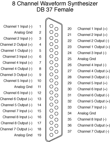
The Waveform Synthesizer inputs accept line level signals (+/-1.5Vmax) but also have adjustable gain configurations of x1, x10, x100, x1000. Gains can currently be set for pairs of inputs only (i.e. channel 1 and 2 will have the same gain setting, 3 and 4 the same, etc.). You can set the input channel gains either through user modifiable fields in each Model Configuration Window, or via the default.cfg configuration file command structure.
Modifying the gains from the Model Configuration window is easy but values won't be saved with the model.
To set the input channel gains in the default.cfg file, the following commands apply:
Note: in the following commands, "n" represents an integer or floating point number; gain values of 1, 10, 100, and 1000 are available; values entered that do not correspond to these numbers will be rounded to the nearest correct gain value (e.g. for n = 600 the gain will be 1000). Variables are bolded.
Commands:
DSPgain = n
Sets all input channels on all DSPs to gain "n".
DSPXgain = n
Sets all input channels corresponding to DSPX to gain "n".
Example:
DSP1gain = 100
sets gains for all 8 input channels on DSP1 to gain 100.
DSPXgainy = n
Sets input channel y on DSPX to gain n. (Currently gains for channel pairs such as 1, 2 or 3, 4 will always be the same).
Example:
DSP1gain3 = 10
sets gains for input 3 and 4 on DSP1 to gain 10.
Input channel gain modification is supported in Model Builder Versions 2.01 and later. Make sure you have installed the latest version of the software we sent. To install Model Builder, place the disk in the a: drive and reboot the machine. At the a: prompt, type 'install'. It is important that you reboot the machine as indicated or else the Model Builder software will not install.
RADIO MODULATION TYPE, 3.06 AND EARLIER
With regard to the modulation field in the various radio objects, use 00010301 for FM and 00010102 for AM. The other modulation types are not yet supported.
DIFFERENCES BETWEEN 3.06 AND 3.08
We reviewed a Custom Model (originally developed in 3.06) under Model Builder Version 3.08 and found a few changes you may need to make if you're in the same situation.
All changes are in the communications model. There are no changes to the aural cue model.
The changes apply if you are controlling signal level and noise floor yourselves rather than letting the DACS provide these effects. Since we have increased the fidelity and added new features in the ratio area, it has affected the model operation slightly. There is no requirement to make any changes to your host software. Changes are listed below:
On Page 1, change the local Power/Mode field from 0 to 1.
Example:
Old (incorrect):
Power/Mode : RDVOPRBL + 0 = 0 Off
New (correct):
Power/Mode : RDVOPRBL + 1 = 0 Off
On page 3, set the following field values on Line 1:
These changes will ensure the radio and receiver objects have a zero noise floor. (This way, you will control all the noise heard through the radio using the local noise source.)
For ALL the Pilot Radio objects (includes Pilot VHF Radio, Pilot UHF Radio) make the following changes:
On Page 1, remove the signal level variable (either RDVAUDIO or RDUAUDIO) from the Antennae Gain field.
The reason for this change is that antennae gain now controls both transmission and reception. Hence if RDVAUDIO were zero during transmission - OOPS! no transmission at all! You will now control single level via the RX Output gain field.
However, you must also include in series the volume control (either RDVVOLUM or RDUVOLUM). This change is detailed below.
Create a 2 variable math function on controls list (you will need 2 - one for each radio). Connect volume control to X input (eg. RDVVOLUM), Signal level variable to Y input. (eg. RDVAUDIO), and a multiply function to the Function input.
On Page 1 of the Radio object, remove the volume control from the RX Output Gain field and connect the new function created in (b). Do not connect this function to the Sidetone or Tune Tone Gain fields. Leave connections as they are.