ASTi Logo

DACS App Note

Remote Interface Unit Diagnostic Testing Using Model Builder Utility 'RIUTEST' (#49)

Test Model Description

  1. The RIUTEST model activates a user-specified RIU. The RIU address is shown as RIU Under Test.
  2. Audio Interface functions:
    • Route a synthesized audio test tone to RIU output channels A, B, C and D.
    • Sequentially activate RIU input channels (A-B-C-D-A...) to receive audio input signals. Only one channel is active at a time--the active period for each channel is 2.5 seconds.
    • During each active input period, the model senses the input signal level. The input signal levels are displayed in the four rows under Audio Test Results, Channel A through Channel D.
    • At any given time the test results will show one active channel with a varying signal level and the three inactive channels with 0.000 levels.
    • If any of the channel levels read 10.000E-09, refer to the Troubleshooting section.
    • The active channel signal level shows two types of readings:
      • With no RIU test plug installed - the model measures the RIU noise floor.
      • With the RIU test plug installed the model measures the RIU noise floor plus the (looped back) signal level of the audio test tone.
    • You can assess audio performance by comparing the signal level measurements to reference levels. A reference level chart is available in this app note (Table 1) and in the model Control list.
  3. Digital Interface functions:
    • Generate active digital outputs (shorted contacts) on channels A, B, C and D.
    • Activate digital inputs on channels A, B, C and D to sense shorted contacts.
    • The digital input states (open with no test plug or shorted with test plug) are displayed under Digital Test Results, Channel A through Channel D.
    • The digital input states are:
      • No RIU test plug installed (open circuit) = 0.000.
      • RIU test plug installed (short circuit) = 1.000.
    • All four digital inputs and outputs are always active.

Test Procedure

  1. Begin the test without the RIU test plug installed.

    Refer to the following annotated display of the Controls List page:
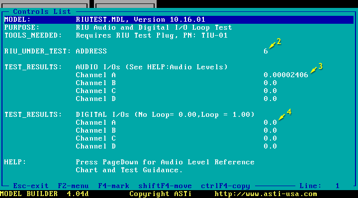

  2. Ensure that the RIU Under Test address matches the RIU address (hardware) switch setting.
    • The example shows RIU address 6 under test.

  3. As the Channel Under Test progresses through the input channels, inspect the TEST RESULTS: AUDIO I/O Channel A through Channel D levels.
    • For reference, the example RIU input gain setting is 0dB.
    • Compare the Channel A level (0.00002) to the 0 dB Open Loop level in Table 1 (0.00002). Channel A levels are in the nominal range.
    • Repeat readings for all four channels.

    Table 1: Nominal Audio Interface Levels
    RIU Input Gain Audio Level: Open Loop Audio Level: Closed Loop
    0 dB 0.00002 0.009
    +20 dB 0.00003 0.09
    +30 dB 0.00005 0.297
    +40 dB 0.0001 0.453
    +60 dB 0.001 0.483

  4. Inspect the TEST RESULTS: DIGITAL I/O.
    • With no loop installed, all four channels should read 0.000.

  5. Connect RIU test plug to the channel under test.

    Refer to the following annotated display of the Controls List page:
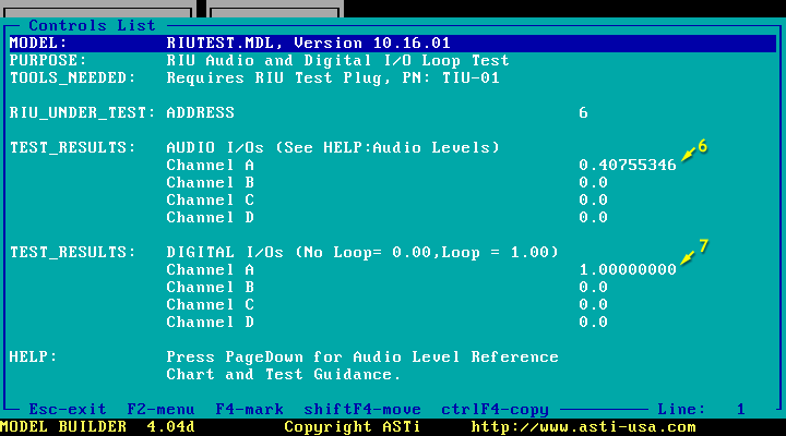
    The example shows the results of connecting a test plug to Channel A.


  6. Inspect the TEST RESULTS: AUDIO, Channel A level.
    • Compare the Channel A audio level reading (0.4) to the 0 dB Closed Loop level in Table 1 (0.4). The level is in the nominal range.
    • This reading proves that the output signal level is correct and that the input channel is functioning properly.

  7. Inspect the TEST RESULTS; DIGITAL I/O Channel A.
    • With the loop installed, the channel reads 1.000.
    • This proves that the digital output and digital input circuit is functioning properly.

  8. Move the test plug to the remaining channels and repeat readings.