

This tutorial focuses on the radio in its simplest form, the local radio. Two operators communicate using local radios on one Telestra server.
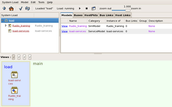
Open a Project, Layout, and Load or create new ones. Then execute the Load.
Open the Load Viewer, right-click and add a new SimModel.
Open the model and add a folder, name it 'Folder1.'
Open 'Folder1' and add the following components:
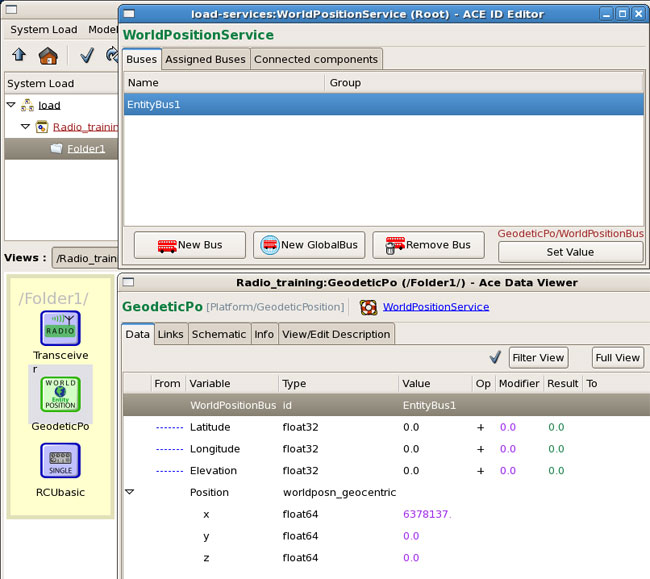
Open the world position component (Geodetic is used for this example) and in the World Position Bus value add an Entity Bus. (Note this must be the same bus set later in the RCU object). Create a New Bus and set the value.
Optional: Set the elevation, latitude, and longitude.
Right-click and copy 'Folder1', then right-click and paste it. Rename it 'Folder2.'
Open 'Folder2' and open the Geodetic component and create a new EntityBus.
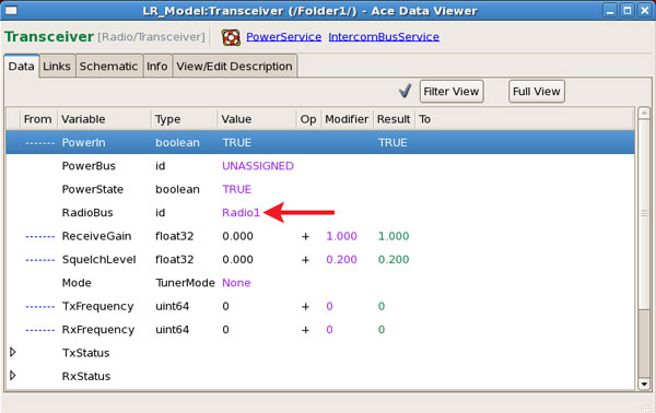
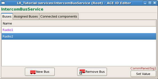
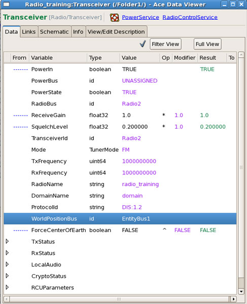
Set the Radio Bus for both Transceivers in 'Folder1' (Radio1) and 'Folder2' (Radio2).
In the model, add a new folder and name it 'Operator1.'
Add a CommPanel > CommPanel4 and assign Sig1 to RadioBus1.
Add an IOInterface > ACE-RIU Channel and set the Identifier value with the ACE-RIU name and Channel to channel A (or to a channel with connected audio peripherals, such as a headset, etc.).
Right-click on the 'Operator1' folder and copy it. Right-click and paste the folder renaming it 'Operator2.'
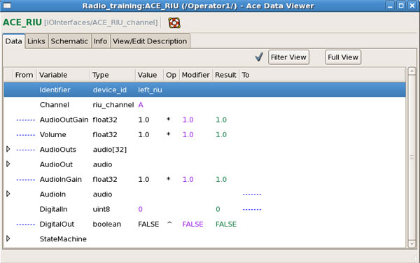

In the 'Operator2' folder, change the CommPanel radio bus to RadioBus2. Also change the ACE-RIU component Channel to channel B (or another channel with connected audio peripherals, such as a headset, etc. ).
Open the Model Link Editor for Operator1 and link the following as shown below:
ACE-RIU using signals DigitalIn/PTT to the CommPanel
ACE-RIU using signals AudioIn/InSignal to the CommPanel
CommPanel using signals OutSignal/AudioOut to the ACE-RIU
CommPanel using signals SideSignal/AudioOut to the ACE-RIU
Note: The link connections may vary depending on ACENet device and PTT type.
Repeat these links for Operator2.
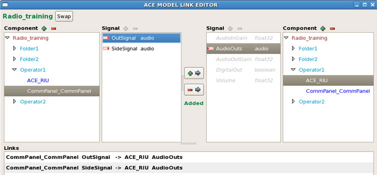
After all links are created, save the load.
Navigate back to the Project's Layout and open the Comm Planner. Expand the default Net and set the Frequency to a realistic number (100000000).
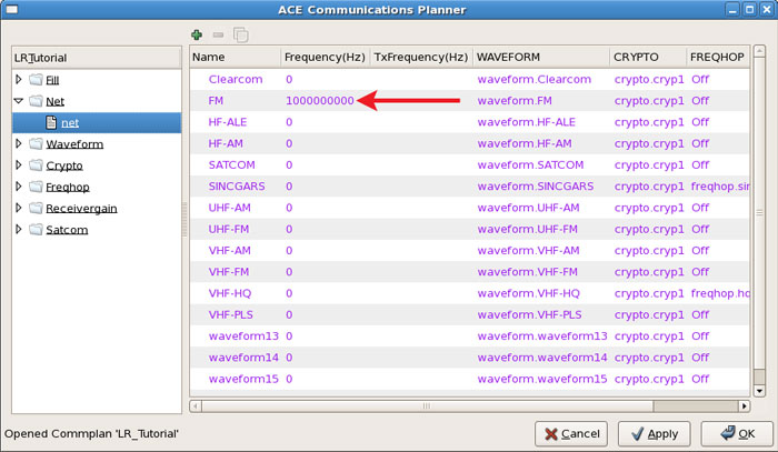
Save the Project and reinstall the Layout.
Navigate back to the model and open 'Folder1', set the Fill in the RCU component by double-clicking the empty area under the 'Value' column. Assign the TransceiverID.
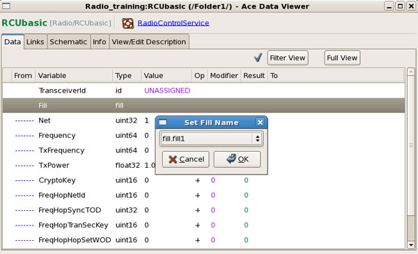
Open the Transceiver and assign the TransceiverID (must be the same as the RCU). Set the Radio Name, Domain Name, Protocol ID, and World Position Bus.
Note: You will have to return to the Project level (Project Manager) and add the Domain using the Domain Editor.
Repeat this step for 'Folder2' using the corresponding bus and radio name.
The model is complete, two operators should be able to communicate through the local radio.